Cables and wiring¶
Every cable on the terraPen is made by hand: cut to length, strip the sheath, crimp a connector onto each core. This page gives the length and the connectors for each lead.
Work in progress
Lines marked to be confirmed are still being checked on a finished machine.
The leads at a glance¶
| Lead | Cable | Length | Device end | Controller end |
|---|---|---|---|---|
| Y motor | 4-core PVC, 26 AWG, flexible, unshielded | 515 mm | JST PH 2.0 6-way | White JST PH 2.0 4-way |
| X motor | 4-core PVC, 26 AWG, flexible, unshielded | 920 mm | JST PH 2.0 6-way | White JST PH 2.0 4-way |
| Z motor | 4 single cores, Alpha Wire 3049 BK001, 26 AWG | 2100 mm | Female JST SM | White JST PH 2.0 4-way, pins 1 to 4 |
| X endstop | 3 single cores, Alpha Wire 3049 BK001, 26 AWG | 2100 mm | Female JST SM | JST PH 2.0 3-way |
| Y endstop | 3-core PVC, 26 AWG | 920 mm | Female JST SM | JST PH 2.0 3-way |
The Y endstop lead is the same length as the X motor lead because the two sit next to each other. The X endstop lead is the same length as the Z motor lead.
Cable slot in the frame¶
A short slot is cut in the lip of the cross-member so the cables can drop into the T-slot underneath. †
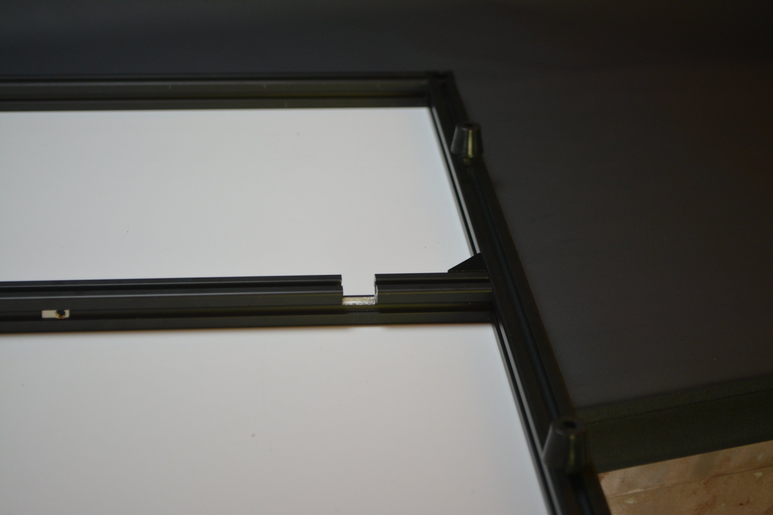
The chain support clip that holds the cables in place is printed from CHAIN_SUPPORT.stl.
X and Y motor leads¶
Use 4-core PVC cable, 26 AWG. It needs to flex, so choose a soft PVC sheath. The cable is unshielded — shielded cable is awkward wherever it has to bend.
- Cut the cable to length: 515 mm for Y and 920 mm for X.
- Strip the sheath: 27 to 30 mm at the motor end and 17 to 20 mm at the controller end. This exposes the four coloured cores.
- Crimp a contact onto each core with a crimping tool.
- Push the contacts into the housings:
- Controller end: a white JST PH 2.0 4-way housing, using pins 1, 2, 3 and 4.
- Motor end: a JST PH 2.0 6-way housing, using pins 1, 3, 4 and 6. Pins 2 and 5 stay empty.
The cores on the cable used for this build are yellow, blue, green and red. Colours vary between suppliers, so always wire by pin position rather than by colour.
The colours themselves do not matter. What matters is that the same core carries the same position at both ends, so that no two cores get crossed.
Z motor lead¶
The Z lead runs through the 7 × 7 energy chain. A sheathed multicore cable does not bend well around the other cables, and a 3-core and a 4-core cable will not both fit in a 7 × 7 chain. So the Z lead is made from four single cores instead.
The wire is Alpha Wire 3049 BK001: 26 AWG, tinned copper, black PVC. Each core is 2100 mm long, which also leaves a little slack.
- Cut four lengths of wire, 2100 mm each.
- Colour-code the cores. The wire is all black, so wrap a thin strip of coloured insulation tape, about 1 mm wide, around both ends of each core, close to the crimp. Use a different colour for each core: this build uses red, green, yellow and blue. The colours themselves do not matter, as long as the same colour is at both ends of a core and no two cores are crossed.
- At the controller end, crimp a white JST PH 2.0 4-way connector, pins 1 to 4.
- At the motor end, crimp a female JST SM connector.
The motor¶
The Z motor is a NEMA 14, the 14HS17-0504S (see the bill of materials). It comes with a bare 300 mm lead rather than a plug-in connector. Cut the lead 30 to 40 mm from the motor, and fit a male JST SM connector. The female on the long Z lead plugs into it.
The motor's own leads are A+ black, A- green, B+ red and B- blue. Note which is which before you cut, so the coils stay paired when you match them to the tape colours.
Endstop leads¶
Both endstops are optical modules with a male JST SM connector. The leads use the female JST SM, which plugs into the module.
- X endstop: three single cores of Alpha Wire 3049, 2100 mm, colour-coded with tape as for the Z lead. It also runs through the energy chain, which is why it is made from single cores.
- Y endstop: 3-core PVC cable, 920 mm.
Check the polarity
The wire order at the controller header must match the pin order on the endstop module. The module is marked SIG, GND, VCC. A lead wired the wrong way round can damage the board or the endstop, so check the pin order at both ends before powering on. The limit switch connectors are J5 for X and J19 for Y — see the controller pinout.
To be confirmed
The pin order for the controller end is still to be confirmed.